80 Amp. to 150 Amp.
according to DIN 43703

Shake It
Shake It

The shunts in this range are built according to DIN 43703 and are supplied on an isolated base upon request for both 60 mV, 100 mV and 150 mV. shunts up to 80 amps voltage drop 60 millivolts are deformed at a radius of 70 ° to reinforce flatness.

TECHNICAL SPECIFICATIONS

Rated Current: 30 to 150 Amp
Voltage drop: 60, 100, 150 mV
Voltage Tolerance: ±0.5% Standard ±0.1% Available*
Mounted on base: Available
Bolt kit: 2 Viti M8x25 + Rondelle e Dadi 2 TC Comby M5x8 Zinc screws. + Washers
Operating Temp: -40°C to +60°C
Storage Temp: -55°C to 80°C
Materials: Resistance element Manganine. Block brass, copper, aluminum

Technical notes

Mounting: Shunts must be installed in a vertical position to favor conventional free flow of air. If vertical mounting is not practical, forced air cooling or adding heat sinks to blocks can reduce the operating temperature. the resistances (manganin) must never exceed + 145 ° C, otherwise permanent changes in resistance could occur.

When a current of 100 A or more passes through the shunt, most of the heat is dissipated to conduct through the shunt terminal blocks in the busbar or connecting cable. Therefore it is necessary to ensure good contact between the branch terminal blocks and the conductor terminals and that the conductors have an adequate cross section to prevent the shunt temperature from exceeding 145 ° C (125 ° C recommended).

If the shunt is mounted in an enclosure, care must be taken to ensure adequate cooling. If the power density is greater than 1/4 watts per inch of the cabinet surface for all enclosed devices, additional cooling in the form of vents or fans must be provided.

The shunts must also be installed in such a way as to protect them from thermal expansion forces produced by busbars or short-circuit forces. Flexible wiring may be required in applications with high pulse current, high vibration or high temperature applications.

Whenever possible, all shunts should be installed on the ground side of the circuit. For greater than 750 VDC, shunts must be installed on the ground side circuit due to the dielectric strength of the shunt base.

Operating Current Derating: For continuous operation, it is recommended that shunts not operate at more than two-thirds (2/3) of the rated current under normal conditions according to IEEE standards for DC instrument shunts. At ambient temperatures above 40 ° C, the current must be further reduced to avoid damage.

Intermittent Operation Shunts that do not pulse continuously and are exposed to pulsing only can be operated at levels at their rated current for short periods of time. The pulses are limited to the maximum blade temperature not exceeding 145 ° C (125 ° C recommended). Many variables such as the ambient temperature, the cross section of the conductors carrying the current and the duration of the pulse make it difficult to calculate exact values. The size of the shunt must be validated by the customer for the impulse current and duty cycle on a case-by-case basis.

Temperature Coefficient of Resistance

Resistance changes with temperature

The temperature coefficient of resistance, or TCR, is one of the main used parameters to characterize a resistor. The TCR defines the change in resistance as a function of the ambient temperature. The common way to express the TCR is in ppm/°C, which stands for parts per million per centigrade degree. The temperature coefficient of resistance is calculated as follows:

Formula temperature coefficient of a resistor: TCR = (R2-R1)e-6 / R1*(T2-T1)

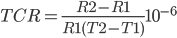
Where TCR is in ppm/°C, R1 is in ohms at room temperature, R2 is resistance at operating temperature in ohms, T1 is the room temperature in °C and T2 is the operating temperature in °C. Often instead of TCR, α is used.

Graph showing average TCR for resistorsAverage TCR ΔR/R in ppm for a temperature range of -55 till 25˚C and 25 till 125˚C

Positive or Negative Temperature Coefficient of Resistance?

Resistors are available with a TCR that is negative, positive, or stable over a certain temperature range. Choosing the right resistor could prevent the need for temperature compensation. In some applications it is desired to have a large TCR, for example to measure temperature. Resistors for these applications are called thermistors, and can have a positive (PTC) or negative temperature coefficient (NTC).

Measuring methods for the TCR

The temperature coefficient of resistance for a resistor is determined by measuring the resistances values over an appropriate temperature range. The TCR is calculated as the average slope of the resistance value over this interval. This is accurate for linear relations, since the TCR is constant at every temperature. However, many materials have a non linear coefficient. For Nichrome for example, a popular alloy for resistors, the relation between temperature and TCR is not linear. Because the TCR is calculated as average slope, it is therefore very important to specify the TCR as well as the temperature interval. The way to measure TCR is standardized in MIL-STD-202 Method 304. With this method, TCR is calculated for the range between -55°C and 25°C and between 25°C and 125°C. Because the highest measured value is defined as TCR, this method often results in over specifying a resistor for less demanding applications.

In the chart below the temperature coefficient of resistance is given for a wide variety of materials. Note that the exact value depends on the purity of the material as well as the temperature.

Material TCR /°C
Manganin 0.048
Constantan 0.000008
Copper 0.0039